
This passive beamforming topology is not well known but is widely used – a common situation in the RF world.
Part 1 was an introduction to the electronic steering of an antenna beam and the Butler matrix; this part continues the investigation.
Q: The Butler passive arrangement seems simpler; why not use it in all cases?
A: A Butler matrix represents a passive, beamforming-feed network for phased-array antenna elements. It faces challenges in achieving wide bandwidth with higher phase-control accuracy due to limitations in the bandwidth of its components.
The factors influencing the bandwidth and performance of the Butler matrix are closely linked to the design of its passive components, with connections between components established through transmission lines. As the number of input and output ports increases in a Butler matrix, so does the complexity and potential lengths of the interconnections.
Every component must support that wide bandwidth with the required phase accuracy, and each path’s electrical length error must be meticulously controlled within a very narrow range. Any deviation in these characteristics leads to significant phase changes over a wide frequency range, presenting major technical challenges.
Butler matrix gets more interest from a long history
Q: Why is the Butler matrix getting more interest and design-ins?
A: There is substantial development effort and activity aimed at extending the capabilities of beamforming technology. Innovations in this technology are needed for 5G (and even 6G), Wi-Fi 6E, IoT, driverless cars, mobile communication, satellite communication, testing, and radar applications.
New developments for wideband Butler matrices include advances in wideband hybrids, wideband passive phase shifters, and accurate phase-matching of cable assemblies. Further, simulation and optimization tools have improved, coupled with advanced manufacturing processes.
Q: When was the Butler matrix concept developed?
A: It was originally designed in the early 1960s by Jesse Butler and Ralph Lowe, and published in an article in Electronic Design (cited as April 12, 1961, pages 170-173), and soon recognized as an innovative distribution network for generating fixed beams in array antennas (I would like to see this article and searched the web extensively to find a scanned copy, but was unsuccessful).
It replaced earlier passive designs since it needed fewer phase shifters. This was a big space and cost saving and increased robustness of the large arrays, typically 64 × 64 elements, in the aircraft defense radars developed at the time.
The work was performed at Sanders Associates in Nashua, New Hampshire (now part of BAE Systems), specializing in complex circuit assemblies on printed circuit boards. While the original article calls the arrangement the “Sanders beam-forming matrix,” it is now only known as the Butler matrix; the reason for the nomenclature transition is another mystery.
Q: For what frequencies is the Butler matrix used?
A: It is typically a good fit from 1 to 10 GHz but has been used at higher frequencies. As operating frequencies increase, the challenge of delivering and maintaining performance increases, as parasitics and other parameter shifts are more subtle and have a larger impact.
Q: What are the top-tier performance metrics here?
A: They are similar to those used for most RF components and functional blocks, such as return loss, insertion loss, amplitude flatness, and phase deviation. These measurements are difficult to make due to the number of ports involved and the complexities of the instrumentation needed. Higher-order matrices have greater losses as they have more components and longer lines.
Make or buy is not an issue
Q: What sort of design analysis is possible?
A: As with all RF designs, analysis is desirable and necessary. This includes intense analytical analysis and associated modeling with complex equations that characterize nominal performance and sensitivity to component tolerances and likely parasitics. Electromagnetic field simulation and modeling tools can provide quantitative insight and other insights. The Butler matrix is analyzed in full detail in advanced RF-design books and papers.
Q: Do you have to custom-build your own Butler matrix?
A: Absolutely not, and it’s probably not a good idea to try. They are available as standard, off-the-shelf items from vendors such as Ranatec, Krytar, Spectrum Control/APITech Weinschel, and MIcable (China), among others. Most vendors will also work with the prospective customer to tailor specifications and tradeoffs or create a semi-custom or full-custom unit. Standard units are available to operate to 10 and even 20 GHz.
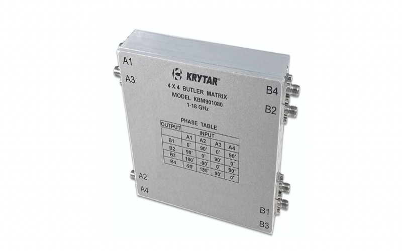
A typical ready-to-use unit is shown in Figure 1; note how the case is fully and clearly labeled.
Figure 1. Butler matrices are available from many vendors as standard packaged products, such as this unit in a case with labeled connectors and a phase table. (Image: Krytar)
Q: What about using a microstrip design rather than discrete elements?
A: Microstrip is an inexpensive solution and is often used where it makes sense regarding frequency, size, and power levels. A microstrip design requires a different approach to providing the matrix components and functions, rather than simply substituting a microstrip-equivalent version of each passive component; also, fabrication tolerances can be a problem at these frequencies,
Microstrip techniques are not suitable for all Butler matrix applications. The reason is that when there are many antenna elements, the signal path through the Butler matrix goes through a large number of hybrids and phase shifters. The cumulative insertion loss from all these components in the microstrip can make it impractical.
Waveguide technology can overcome this problem, especially at higher frequencies and power levels, with far lower losses. However, it is more expensive, bulkier, and heavier, so it is not a good fit for aircraft use.
Conclusion
The Butler matrix is a very clever, non-obvious way to implement a steerable antenna array using passive components. It offers some clear advantages to alternatives but also has some limitations. Since it was first presented in 1961, it has been used in many real-world systems with considerable success.
References
The Butler Matrix and its Use for Beamforming and MIMO Testing, Everything RF, EverythingRF
Butler Matrix, Microwaves101
Butler Matrix, Wikipedia
Butler Matrices and RF Switches, Spectrum Control
Wideband Butler Matrices and Their Potential Applications, MIcable
Butler Matrix KBM9010180, Krytar
Related EE World Online content
Creating 5G massive MIMO: Part 1
Creating massive MIMO, part 2
How many types of radar are there?
Module simulates 8×8 MIMO for 5G testing
Difference between a waveguide and transmission line
VSWR and impedance, Part 6: Microstrip and stripline